- Set it up so that I could use it with the Maple integrated development environment ('IDE') - a simple IDE that allows a 'fast-start' and that comes with quite a few 'example' programmes to show the capability of the device, and also provide a basis for one's own projects.
- Programmed it to make some LEDs flash on and off in different sequences
- Set it up so that I could use it with the Eclipse IDE - a much more powerful IDE that provides more flexibility (at the cost of more risk of doing something that can't be easily undone)
- Programmed it again using Eclipse to make the LEDs flash on and off, using a JTAG interface
- Worked out how to return the board to being able to work with the Maple IDE (since using the Eclipse IDE to download code removed the bootloader that the Maple tool requires)
This last bit was quite tricky and not all that obvious! So a description follows for anyone out there trying to work out how to make this work... especially as most of the instructions I could find are Linux-based, so I made sure I could do this using the Eclipse IDE on my windows machines too!
Note that all of this assumes that you've already set up Eclipse, the various drivers and other software required and have a JTAG interface to hand!
Firstly you need to make sure that you have copied the OpenOCD files and the Olimex examples into a folder structure that mimics that found under your 'Program Files' folder, and make this your workspace (short paths with no spaces are better, mmm-kay?):

Next, go download the Maple bootloader source and unzip it. Move the folder named something like 'leaflabs-maple-bootloader-d1234348' (yours will have a different name) into your workspace folder and rename it to something a little shorter, I called mine, 'stdBoot' (you can see this in the image above).
In Eclipse right-click in the projects pane and select 'Import', click on 'C/C++' and then select 'Existing Code as Makefile Project' and click 'Next':


For the 'existing code location' browse to the 'stdBoot' (or whatever you called it) folder, and select just this folder:

Click on 'Finish'. The folder and contents should then appear in the projects pane. 'Borrow' (copy and paste) the stm32.cfg and

OK, almost there! If you've not done so already then hook up your board to your computer via the JTAG. You also need to power the board - to do this I use a USB lead that is broken and supplies only power (otherwise the PC will try to load the USB drivers that the JTAG needs and reserve them!).
Try clicking the 'Run external tool' entry in Eclipse that matches your JTAG interface (for me this is the ARM-USB-TINY-H), if you get an error like this:

Then just click in the pane holding 'main.c' and try again, what you should see is this:

Which appears in the console panel end finishes something like: "stm32.cpu: hardware has 6 breakpoints, 4 watchpoints". This is good and means that everything is running,
Ensuring that you're in the C/C++ perspective of Eclipse, expand your 'stdBoot' project and open the 'Makefile' - on my PC the make action failed to make some folders, so look through for 'mkdir' commands and create the folders that make will require. Unless you know exactly what you are doing, DO NOT EDIT THE MAKEFILE! In my Makefile, the mkdir commands are:


Now right click on the 'stdBoot' project and select

Now select the 'all' entry in the 'Make Targets' window and click on 'Build'.
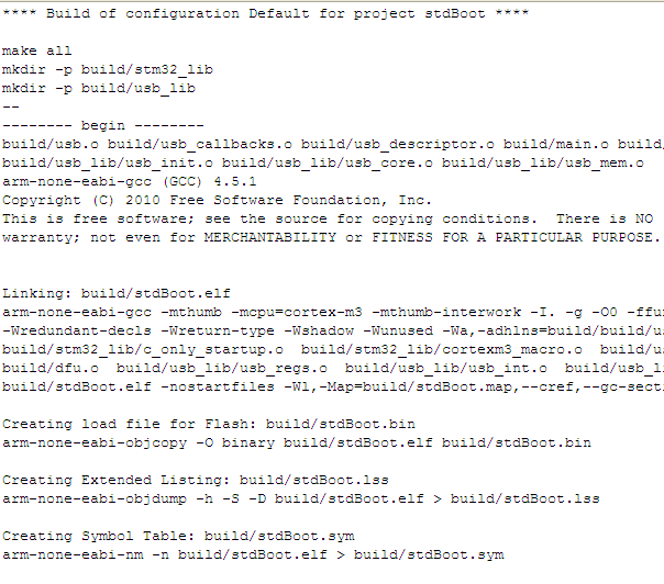
If your setup is OK then you'll see a successful build occur. Warnings are undesirable, but survivable - 'Errors' though are a big problem! Check the console carefully - if you've had a successful build then you will receive a report of the file sizes created. If you see errors, then Google is your friend! A good outcome looks like this (just cancel any errors from 'mkdir.exe' as we've already circumvented these):


Fill out the Debug configuration name and there are now some tabs to fill out:
- On the first tab, 'Main', in the C/C++ application box type: build/stdBoot.bin

- On the second tab, 'Debugger', in the 'GDB debugger' box type: arm-none-eabi-gdb (if you've not added the yagarto/bin folder to your path then browse to that file)

- On the third tab, in the 'Run' commands type:
target remote localhost:3333
monitor reset halt
monitor wait_halt
monitor sleep 100
monitor poll
monitor flash probe 0
monitor flash write_image erase main.bin 0x08000000
- On the 4th and 5th tabs do nothing (you can 'add to favourites' on the 6th tab if you want to)
I know this is quite long, so
