Thursday, 27 December 2012
Some quick thoughts on Christmas
What I love about Christmas is the way that it has become a celebration of children and childhood, despite the rampaging commercialism and materialism that are slathered over it by the bucketload. This was first pointed out to me by an Israeli I met around 8 years ago, and every year I am reminded of it. In his words, "I love Christmas, it is like a celebration of childhood, I wish we had something like it at home".
I often think about this and how true this is if you just look at things from a slightly different angle, and if anything the biggest parts of childhood that are celebrated are trust and innocence.
What do I mean? Well even in these paranoid times it's OK for young children to go up to a total stranger and sit on their knee to talk to them at Christmas, and that it's OK for us to tell the children that said stranger will then come into their bedrooms late at night after breaking into the house to bring them sweets and gifts.
Can you imagine doing and saying those things at any other time of the year? Children going off to talk to a stranger is the stuff of most parents' nightmares (let alone their child trying to sit on a stranger!), and similarly, sneaking into childrens' bedrooms at night tends to be an unpopular choice of activity for adults. But at Christmas it's all OK, because the stranger in question will be bearing gifts and sweets for the children (provided that the children have been 'good')! Compare that the 'stranger danger' message that we give throughout the rest of the year.
Yes, this is the commercial side of Christmas, yes it's materialistic, but look at what underlies it.
Spending a Christmas with my young niece and nephew (5 and 7 respectively) showed me this "celebration of childhood" again this year, after all the unwrapping was done and the dinner was eaten all my niece wanted to do was wear a "princess dress". My nephew? All he wanted to do was go outside and kick a ball around, because he'd been promised he could do that every day while he was off school.
Friday, 3 August 2012
The project continues!
So I'm now about a year into my MSc project and progress is, well, good :-)
I'm pretty much finished and I'll probably be publishing some papers based off my work if my supervisor has his way.
So what have I done? Well I've used the Fuzzy-Transform (F-transform) in a way, which as far as I can see, has never been done before. I've also managed to predict the range of an electric vehicle successfully, which is nice!
Hopefully once I've published any papers that will come out of my project I will be able to share what I've done a little more publicly, but for now I'm afraid things have to stay secret!
Tuesday, 22 May 2012
Thoughts on requirements!
Don't ask where this has come from, just accept that it has come ;-)
The key to good software engineering is good requirements management, and this must come from both sides.
Poor customer requirements (no matter how aggressively chased by the software provider) will always lead to "to-ing and fro-ing" and exasperation on both sides, no matter how good the provider is.
I know of software providers who have been described as "useless", by one customer (who as an organisation never really knew what they wanted, or had any ability to express their desires in good, unambiguous requirements) and "excellent", by another customer (who had a very clearly documented set of requirements that had been fully agreed internally before issue)!
The image at the top of this Building Better Software blog summarizes the situation in some case quite well. It's easy to laugh at this image, but it's a real issue that people (who sometimes should know much better) sometimes really don't know what they need (they all know what they want!).
For example, I know of a project that required data from vehicles captured at 5 second intervals. No problem, easy in fact with the proliferation of CAN bus. But the vehicles were electric and the customer wanted to analyse how much energy was being recovered through regenerative braking, and basic application of the Nyquist Shannon theorem says that with a 5 second sample time only events of 10 seconds or greater duration could be reliably captured. So guess what? Next to no regenerative braking events were captured and the customer started trying to tell the vehicle manufacturer that the vehicles were faulty as they weren't performing regenerative braking as advertised. All because the customer didn't tell the software provider what they wanted to do with the data, just that they wanted data collected at a certain interval (the customer then went back to the software provider and requested free changes since it was "obvious" what they wanted to do with the data... but that's another story!).
Of course feature-creep is also a problem - adding kludges in an attempt to "make a tweak" to keep a customer happy will only lead to borked systems. Customers need to be quoted, and need to expect to have to pay if they want changes or increases to a system's capability so that the work can be correctly undertaken.
Finally, competing documentation "standards" can make things worse. From diagrammatic through to natural language (sometimes including metaphor and simile) lots of people have differing ideas on what makes "good requirements", and the gamut runs from UML, SysML, SDL through to RFC2119-based prose and "user stories". In fact this XKCD applies quite nicely.
Friday, 13 April 2012
Booting up
Edited: 20120413 to add images and fix some errors.
OK, so today was fun, I received my Olimexino-STM32 that I talked about yesterday and I was able to do a few things with it:
This last bit was quite tricky and not all that obvious! So a description follows for anyone out there trying to work out how to make this work... especially as most of the instructions I could find are Linux-based, so I made sure I could do this using the Eclipse IDE on my windows machines too!
Note that all of this assumes that you've already set up Eclipse, the various drivers and other software required and have a JTAG interface to hand!
Firstly you need to make sure that you have copied the OpenOCD files and the Olimex examples into a folder structure that mimics that found under your 'Program Files' folder, and make this your workspace (short paths with no spaces are better, mmm-kay?):

Next, go download the Maple bootloader source and unzip it. Move the folder named something like 'leaflabs-maple-bootloader-d1234348' (yours will have a different name) into your workspace folder and rename it to something a little shorter, I called mine, 'stdBoot' (you can see this in the image above).
In Eclipse right-click in the projects pane and select 'Import', click on 'C/C++' and then select 'Existing Code as Makefile Project' and click 'Next':


For the 'existing code location' browse to the 'stdBoot' (or whatever you called it) folder, and select just this folder:

Click on 'Finish'. The folder and contents should then appear in the projects pane. 'Borrow' (copy and paste) the stm32.cfg andopenocd.cfg project.cfg files from one of the other STM32 projects for your 'stdBoot' folder:

OK, almost there! If you've not done so already then hook up your board to your computer via the JTAG. You also need to power the board - to do this I use a USB lead that is broken and supplies only power (otherwise the PC will try to load the USB drivers that the JTAG needs and reserve them!).
Try clicking the 'Run external tool' entry in Eclipse that matches your JTAG interface (for me this is the ARM-USB-TINY-H), if you get an error like this:

Then just click in the pane holding 'main.c' and try again, what you should see is this:

Which appears in the console panel end finishes something like: "stm32.cpu: hardware has 6 breakpoints, 4 watchpoints". This is good and means that everything is running,
Ensuring that you're in the C/C++ perspective of Eclipse, expand your 'stdBoot' project and open the 'Makefile' - on my PC the make action failed to make some folders, so look through for 'mkdir' commands and create the folders that make will require. Unless you know exactly what you are doing, DO NOT EDIT THE MAKEFILE! In my Makefile, the mkdir commands are:


Now right click on the 'stdBoot' project and select'Build as...' 'Make Targets'/'Build', in the dialog that appears, click on 'Add', then in the top text entry box type 'all' (without the ''), then click 'OK':

Now select the 'all' entry in the 'Make Targets' window and click on 'Build'.
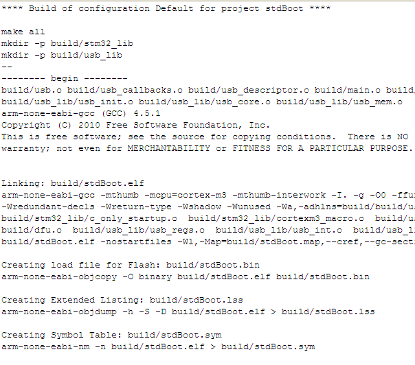
If your setup is OK then you'll see a successful build occur. Warnings are undesirable, but survivable - 'Errors' though are a big problem! Check the console carefully - if you've had a successful build then you will receive a report of the file sizes created. If you see errors, then Google is your friend! A good outcome looks like this (just cancel any errors from 'mkdir.exe' as we've already circumvented these):

Now, right-click your project and under 'Debug as...' select the 'Debug configuration' option. In the new window select 'Zylin Embedded Debug (Native)' and click the 'New launch configuration icon' button:

Fill out the Debug configuration name and there are now some tabs to fill out:


target remote localhost:3333
monitor gdb_breakpoint_override hard
monitor soft_reset_halt
symbol-file build/stdBoot.bin
break main
target remote localhost:3333
monitor reset halt
monitor wait_halt
monitor sleep 100
monitor poll
monitor flash probe 0
monitor flash write_image erase main.bin 0x08000000
I know this is quite long, soif I can I'll add some explanatory images I hope the images are useful!
- Set it up so that I could use it with the Maple integrated development environment ('IDE') - a simple IDE that allows a 'fast-start' and that comes with quite a few 'example' programmes to show the capability of the device, and also provide a basis for one's own projects.
- Programmed it to make some LEDs flash on and off in different sequences
- Set it up so that I could use it with the Eclipse IDE - a much more powerful IDE that provides more flexibility (at the cost of more risk of doing something that can't be easily undone)
- Programmed it again using Eclipse to make the LEDs flash on and off, using a JTAG interface
- Worked out how to return the board to being able to work with the Maple IDE (since using the Eclipse IDE to download code removed the bootloader that the Maple tool requires)
This last bit was quite tricky and not all that obvious! So a description follows for anyone out there trying to work out how to make this work... especially as most of the instructions I could find are Linux-based, so I made sure I could do this using the Eclipse IDE on my windows machines too!
Note that all of this assumes that you've already set up Eclipse, the various drivers and other software required and have a JTAG interface to hand!
Firstly you need to make sure that you have copied the OpenOCD files and the Olimex examples into a folder structure that mimics that found under your 'Program Files' folder, and make this your workspace (short paths with no spaces are better, mmm-kay?):
Next, go download the Maple bootloader source and unzip it. Move the folder named something like 'leaflabs-maple-bootloader-d1234348' (yours will have a different name) into your workspace folder and rename it to something a little shorter, I called mine, 'stdBoot' (you can see this in the image above).
In Eclipse right-click in the projects pane and select 'Import', click on 'C/C++' and then select 'Existing Code as Makefile Project' and click 'Next':
For the 'existing code location' browse to the 'stdBoot' (or whatever you called it) folder, and select just this folder:
Click on 'Finish'. The folder and contents should then appear in the projects pane. 'Borrow' (copy and paste) the stm32.cfg and
OK, almost there! If you've not done so already then hook up your board to your computer via the JTAG. You also need to power the board - to do this I use a USB lead that is broken and supplies only power (otherwise the PC will try to load the USB drivers that the JTAG needs and reserve them!).
Try clicking the 'Run external tool' entry in Eclipse that matches your JTAG interface (for me this is the ARM-USB-TINY-H), if you get an error like this:
Then just click in the pane holding 'main.c' and try again, what you should see is this:
Which appears in the console panel end finishes something like: "stm32.cpu: hardware has 6 breakpoints, 4 watchpoints". This is good and means that everything is running,
Ensuring that you're in the C/C++ perspective of Eclipse, expand your 'stdBoot' project and open the 'Makefile' - on my PC the make action failed to make some folders, so look through for 'mkdir' commands and create the folders that make will require. Unless you know exactly what you are doing, DO NOT EDIT THE MAKEFILE! In my Makefile, the mkdir commands are:
Now right click on the 'stdBoot' project and select
Now select the 'all' entry in the 'Make Targets' window and click on 'Build'.
If your setup is OK then you'll see a successful build occur. Warnings are undesirable, but survivable - 'Errors' though are a big problem! Check the console carefully - if you've had a successful build then you will receive a report of the file sizes created. If you see errors, then Google is your friend! A good outcome looks like this (just cancel any errors from 'mkdir.exe' as we've already circumvented these):

Fill out the Debug configuration name and there are now some tabs to fill out:
- On the first tab, 'Main', in the C/C++ application box type: build/stdBoot.bin
- On the second tab, 'Debugger', in the 'GDB debugger' box type: arm-none-eabi-gdb (if you've not added the yagarto/bin folder to your path then browse to that file)

- On the third tab, in the 'Run' commands type:
target remote localhost:3333
monitor reset halt
monitor wait_halt
monitor sleep 100
monitor poll
monitor flash probe 0
monitor flash write_image erase main.bin 0x08000000
- On the 4th and 5th tabs do nothing (you can 'add to favourites' on the 6th tab if you want to)
I know this is quite long, so
Tuesday, 10 April 2012
Stay on target!
OK so I'm now into the implementation phase of my MSc project - see my previous post on the fuzzy transform for what I was doing a while ago. Because my end-result is for a device to go into a vehicle I need to work in an embedded environment (my target environment) to accurately determine the capability of my system. If you're interested the target platform I'll be using it's called the Olimexino-STM32 and it's made by Olimex.
Over the last few weeks I've found that there's an active community developing small systems using this and other devices, which is useful since it means there are other people doing things that I can learn from and also ensure that I don't inadvertently replicate anything that's already being worked on.
As part of my project I need to do some prediction work, one way of doing this is the method of least squares, and I've described an approach to it in the linked PDF: Using least squares with a linear system
Whether this is the approach I'll end up with is debatable, as the fuzzy transform may still have a few treats in store for me!

'Using least squares with a linear system' by Iain Cunningham is licensed under a Creative Commons Attribution-ShareAlike 3.0 Unported License.
Over the last few weeks I've found that there's an active community developing small systems using this and other devices, which is useful since it means there are other people doing things that I can learn from and also ensure that I don't inadvertently replicate anything that's already being worked on.
As part of my project I need to do some prediction work, one way of doing this is the method of least squares, and I've described an approach to it in the linked PDF: Using least squares with a linear system
Whether this is the approach I'll end up with is debatable, as the fuzzy transform may still have a few treats in store for me!
'Using least squares with a linear system' by Iain Cunningham is licensed under a Creative Commons Attribution-ShareAlike 3.0 Unported License.
Tuesday, 10 January 2012
I feel all fuzzy inside...
Just kidding.
I've not been around much recently as I've been working hard at my MSc project. For part of this I've had to implement something called a "Fuzzy Transform", this was initially presented by Irina Perfilieva and has been developed by the Institute for Research and Applications of Fuzzy Modeling (IRAFM) at the University of Ostrava in Ostrava in the Czech Republic.
The way in which I'm presently using the Fuzzy Transform is one that provides a numerical analysis method that is a cross between fuzzy logic and a filtering function (a filtering function is used to remove noise [unwanted information] from a signal; such functions are in use everywhere in our modern world, from cellphones to missile guidance systems). It's a numerical method, because it doesn't try to "guess" what gave rise to the original data (methods that try to work out what gave rise to the data in the first place are "estimators" and tend to use "mathematical models" to represent whatever is generating the data from a given input); if you wanted to you could feed in a totally random stream of numbers and a numerical method would have a good go at approximating the numbers "with arbitrary accuracy" (this means "as well as you make it", see below).
One of the things that the fuzzy transform provides as well as the filtering capability of the filtering function is an ability called "Universal Approximation", this means that provided any series of data a correctly set-up fuzzy transform can be used to approximate the data. Universal Approximators are useful since they allow you to do all kinds of fun stuff, such as pattern matching (for example, character recognition and face recognition), data compression and forecasting... but more on this later.
So, let's take a varying series of data:

This isn't of anything very exciting other than something that provides a nice wiggly line (if you're really interested it's y=sin(x.π)+x with added zero mean, normally distributed noise with variance 0.01). So what happens if we use the fuzzy transform? We get a plot a little like this:

The blue line in the above plot is the result of the Fuzzy Transform, this was obtained by dividing the original wiggly line into 10 horizontally measured sections, or partitions, taking the Fuzzy Transform of the data and then inverting (reversing) the transform; and you can see that it kind of matches the original wavy line, but as well as removing all the noise, the F-Transform has also removed a lot of the shape of the original line (we've lost information). Using 20 partitions gives this:

Which uses the same colours for the noisy data and the approximation as previously and is a better fit, but still leaves a few gaps. While using 30 partitions gives this:

Which again uses the same colours for the noisy data and the approximation as previously and almost exactly matches the original function, which I've plotted below (in green) along with the 30-partition approximation to allow an easy comparison:

So what does this mean? It means that the Fuzzy Transform can approximate the data "with arbitrary accuracy", which we can now see is a way of saying that it can match the data we feed into it (the red line) as closely as we want it to. Why might we not want to try to get an exact match? Well, firstly, the more accurate we make the approximation, the more calculations are required and so it takes longer to get the approximation, and, secondly, if we make the approximation too accurate then it will also start to approximate the noise (the Fuzzy Transform doesn't know where the data has come from, so it can't tell what is "noise" and what is "signal"). This means that we need to find a balance between ease of calculation, and being a good enough approximation, while still "filtering out" the noise.
In the example above, doubling our "effort" by going from 10 to 20 partitions gives quite a large benefit, but putting in another half as much effort again to get from 20 to 30 partitions doesn't give a very big improvement (so if the end use could tolerate the inaccuracy of the 20 partition transform then we'd use that rather than "wasting effort").
Finally, I suppose you want to know how can this be used? Well IRAFM and others have shown how the Fuzzy Transform can be used to detect patterns and relationships that underlie quite complex data. For example, in one paper published in 2008 [subscription required] the Fuzzy Transform was used to provide a model of the GDP of the Czech Republic based on a set of other data, such as unemployment, the rate of inflation, etc. The Fuzzy Transform has also been used to automatically combine multiple images to provide an image that is of better quality overall than the constituent images [PDF]. Pretty impressive, eh?
If you want to learn more about the Fuzzy Transform, or the other things that IRAFM are involved in researching and developing then they have an extensive list of publications that are publicly available in PDF format.
This may be a bit technical, so please ask questions, I'll do my best to explain, or point you to somewhere you can find more information!
I've not been around much recently as I've been working hard at my MSc project. For part of this I've had to implement something called a "Fuzzy Transform", this was initially presented by Irina Perfilieva and has been developed by the Institute for Research and Applications of Fuzzy Modeling (IRAFM) at the University of Ostrava in Ostrava in the Czech Republic.
The way in which I'm presently using the Fuzzy Transform is one that provides a numerical analysis method that is a cross between fuzzy logic and a filtering function (a filtering function is used to remove noise [unwanted information] from a signal; such functions are in use everywhere in our modern world, from cellphones to missile guidance systems). It's a numerical method, because it doesn't try to "guess" what gave rise to the original data (methods that try to work out what gave rise to the data in the first place are "estimators" and tend to use "mathematical models" to represent whatever is generating the data from a given input); if you wanted to you could feed in a totally random stream of numbers and a numerical method would have a good go at approximating the numbers "with arbitrary accuracy" (this means "as well as you make it", see below).
One of the things that the fuzzy transform provides as well as the filtering capability of the filtering function is an ability called "Universal Approximation", this means that provided any series of data a correctly set-up fuzzy transform can be used to approximate the data. Universal Approximators are useful since they allow you to do all kinds of fun stuff, such as pattern matching (for example, character recognition and face recognition), data compression and forecasting... but more on this later.
So, let's take a varying series of data:
This isn't of anything very exciting other than something that provides a nice wiggly line (if you're really interested it's y=sin(x.π)+x with added zero mean, normally distributed noise with variance 0.01). So what happens if we use the fuzzy transform? We get a plot a little like this:
The blue line in the above plot is the result of the Fuzzy Transform, this was obtained by dividing the original wiggly line into 10 horizontally measured sections, or partitions, taking the Fuzzy Transform of the data and then inverting (reversing) the transform; and you can see that it kind of matches the original wavy line, but as well as removing all the noise, the F-Transform has also removed a lot of the shape of the original line (we've lost information). Using 20 partitions gives this:
Which uses the same colours for the noisy data and the approximation as previously and is a better fit, but still leaves a few gaps. While using 30 partitions gives this:
Which again uses the same colours for the noisy data and the approximation as previously and almost exactly matches the original function, which I've plotted below (in green) along with the 30-partition approximation to allow an easy comparison:
So what does this mean? It means that the Fuzzy Transform can approximate the data "with arbitrary accuracy", which we can now see is a way of saying that it can match the data we feed into it (the red line) as closely as we want it to. Why might we not want to try to get an exact match? Well, firstly, the more accurate we make the approximation, the more calculations are required and so it takes longer to get the approximation, and, secondly, if we make the approximation too accurate then it will also start to approximate the noise (the Fuzzy Transform doesn't know where the data has come from, so it can't tell what is "noise" and what is "signal"). This means that we need to find a balance between ease of calculation, and being a good enough approximation, while still "filtering out" the noise.
In the example above, doubling our "effort" by going from 10 to 20 partitions gives quite a large benefit, but putting in another half as much effort again to get from 20 to 30 partitions doesn't give a very big improvement (so if the end use could tolerate the inaccuracy of the 20 partition transform then we'd use that rather than "wasting effort").
Finally, I suppose you want to know how can this be used? Well IRAFM and others have shown how the Fuzzy Transform can be used to detect patterns and relationships that underlie quite complex data. For example, in one paper published in 2008 [subscription required] the Fuzzy Transform was used to provide a model of the GDP of the Czech Republic based on a set of other data, such as unemployment, the rate of inflation, etc. The Fuzzy Transform has also been used to automatically combine multiple images to provide an image that is of better quality overall than the constituent images [PDF]. Pretty impressive, eh?
If you want to learn more about the Fuzzy Transform, or the other things that IRAFM are involved in researching and developing then they have an extensive list of publications that are publicly available in PDF format.
This may be a bit technical, so please ask questions, I'll do my best to explain, or point you to somewhere you can find more information!
Subscribe to:
Posts (Atom)